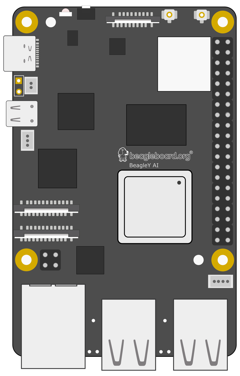
Pinout!
The BeagleY-AI GPIO pinout guide.
This GPIO Pinout is an interactive reference to the BeagleY-AI GPIO pins, and a guide to the BeagleY-AI's GPIO interfaces. Pinout also includes hundreds of pinouts for BeagleY-AI add-on boards, HATs and pHATs.
What do these numbers mean?
- GPIO - General Purpose Input/Output, aka "BCM" or "Broadcom". These are the big numbers, e.g. "GPIO 22". You'll use these with RPi.GPIO and GPIO Zero.
- Physical - or "Board" correspond to the pin's physical location on the header. These are the small numbers next to the header, e.g. "Physical Pin 15".
- SoC - or "Schematic" pins that match the actual processor. These are shown as a tooltip when you mouse over a pin.
What's the orientation of this pinout?
Pinout depicts pin 1 in the top left corner. Pin 1 is the only pin with a square solder pad, which may only be visible from the underside of your BeagleY-AI. If you orient your BeagleY-AI such that you are looking at the top with the GPIO on the right and HDMI port(s) on the left, your orientation will match Pinout.
More Resources
For Support:
Software & Design Files:
Processor Documentation (AM67A):
